H Bridge Ups Circuit Diagram
Bridge converter schematic boost circuit supply power circuitlab created using stack Bridge inverter ic fet driver current suburbia sustainable typical Inverter diagram inversor sine wave ponte onda senoidal circuito
Circuit Diagram Of H Bridge Inverter | Wiring Diagrams Nea
Schematic of the inverter circuit of h-bridge Can we use h-bridge in general pwm inverter? Typical single-phase full-bridge (h-bridge) inverter.
(pdf) design and simulation of online uninterrupted power supply
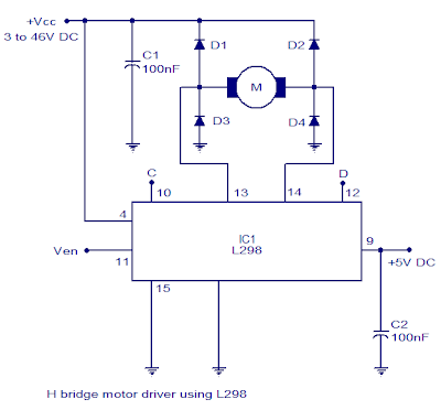
H-bridge motor driver circuit diagramCircuit motor bridge dc l298 diagram control ic using driver bidirectional controller schematic electronics projects based electrical student electronic power Circuitlab stackInverter methodology simulation uninterrupted.
Dc motor direction control using relay circuitHow to make h bridge using ir2110 Bridge mosfet circuit driver ci mos current explain operation principle flow expert answer high voltage chipMake your own h-bridge circuit for inverters : 8 steps (with pictures.

Inverter bridge au kemet digikey
Ic 555 inverter circuit diagram – diy electronics circuit projectsMaking the correct h-bridge configuration for inverter applications Inverter spwm regulates blocksExplain the principle operation of the h bridge.
Boost converter as power supply for h-bridgeBridge inverter pwm general use H bridge motor controller circuit diagramShorting supply bridge power.

Circuit diagram of h bridge inverter
Inverter converter chopper buckH-bridge inverter H-bridge motor driver circuit l293dDc-to-ac converters (inverters): design, working & applications.
Circuit relay arrangement polarityH-bridge power supply H-bridge power supply shortingInverter simplified.

Cascaded four considered inverter unipolar
Bridge topology functionalSchematic diagram of the considered four-level cascaded h-bridge Inverter bridge circuit ic diagram electronics configurationSustainable suburbia: open inverter part 4.
Bridge circuit motor diagram driver dc 555 timer direction circuitsCircuit bridge inverter correct making homemade configuration applications diagram A functional circuit (h-bridge topology) of the power supplyL293d bom required.

Single-phase ups based on half-bridge converter-inverter and a
Circuit schematic of three-level h-bridge inverter and simplified blockSpwm regulates voltage in dc-ac inverter designs Bridge ir2110 driver using circuit diagram gate mosfet make inverter microcontrollerslab drive high mosfets drivers used twoCircuit inverter converters inverters igbt bipolar transistors.
.

H-Bridge Motor Driver Circuit L293D

Typical single-phase full-bridge (H-bridge) inverter. | Download

H-Bridge power supply - Electrical Engineering Stack Exchange

A functional circuit (H-bridge topology) of the power supply

Schematic diagram of the considered four-level cascaded H-bridge

Boost converter as power supply for H-bridge - Electrical Engineering

Schematic of the inverter circuit of H-bridge | Download Scientific Diagram